Thank you for purchasing our patented GET’M Performance Piston Cooling System Installation Kit. Please take time to read these instructions thoroughly before beginning installation.
This kit should include:
- Aluminum Drill Fixture(s)
- 1 - drill tap 8-32 thread [PCD-832]
- 1 - plug tap 8-32 thread [PCT-832]
- 1 - 6” [PCD-6] or 12” [PCD-12] drill bit #28 (LS & BBC engine blocks require a 12” long drill bit in order to clear the raised oil pan rail. All others use a 6” drill bit.)
NOTE: Piston Cooling Jets sold separately.
IMPORTANT: FOR SBC INSTALLATIONS -- Be sure that you have the correct rear main drill fixture for wet or dry sump applications. Wet sump engines will have a ‘W’ beside the part number of the fixture. Please call if you have any questions. Thank you!
Locate the proper aluminum drill fixture for each cylinder. Position the engine block so that the main bearing bores and oil pan rails are facing up. (Main caps should be removed.) Install the appropriate fixture into the main housing bore with the fixture pilot hole facing the correct cylinder. Bolt the fixture to the engine block using either bolts or main studs. Torque to approximately 20-25 ft. lbs. each. NOTE: There are so many different main bolt/stud locations for each engine block of the same brand and cubic inch, that it would be virtually impossible to manufacture and stock fixtures for each type. Therefore, a compromise of sorts had to be reached during the design of the fixtures, particularly for the rear main bearing fixture (typically cylinder #8), which is why the mounting holes are elongated and enlarged. Be sure that the fixture(s), when bolted to the engine block, are aligned parallel to the machined areas for the crankshaft counterweights. In some cases, the fixture holes may need to be notched out even further than manufactured. This will not present an alignment problem. A good rule of thumb is to position each fixture so that the drilled hole will be as close to the centerline of the housing bore as the mounting holes will allow.
After bolting the correct fixture in place, double check the cylinder #. Using an electric hand drill with the supplied #28 drill bit in place, position the drill bit into the hardened busing inside the aluminum drill fixture. Continue drilling through the main webbing until the drill bit goes through into the base of the cylinder. NOTE: It is imperative that the drill bit be removed from the fixture and the flutes cleared often during each drilling operation! Failure to do this step will result in a broken drill bit. Do not use cutting fluid while drilling cast iron engine blocks. The fluid will keep the flutes clogged with metal. Use this same procedure for each cylinder.
After each cylinder has been drilled, remove the aluminum fixture block(s) and lightly de-burr each hole. Do not use a drill-driven countersink for de-burring! A sharp X-Acto type blade or a similar tool should be utilized for removing burrs left from drilling. Then, using the supplied 8-32 drill-tap, begin the threading operation. The drill-tap is primarily utilized as a starting guide for threading the hole. Use the drill bit portion of this centering tap to align the tool, and then begin to tap each hole to a depth of approximately 3-4 revolutions. Do not attempt to finish threading each hole with this tool, as the drill taps are prone to breakage.
The supplied 8-32 plug tap is then utilized for the finish threading. This the most critical operation! The metering jet depth is set by how far the threads extend into the drilled hole (6-7 revolutions is generally correct). A certain amount of trial and error should be used on this process until you become familiar with what depth should be set so that each jet protrudes slightly into the cylinder area. Do not tap the threads into the cylinder area. The end of the threads is what keeps the metering jet from rotating into the cylinder during assembly.
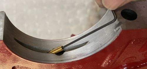
Be sure to lightly de-burr each end of the finished holes. On some engines depending on the bore size, it may be necessary to relieve the base of the cylinder for the oil stream to clear this area. (Before installing the metering jet, take a length of 3/32-inch welding rod (not supplied), insert it through each hole and be sure that there is no interference. This will also show you where the oil stream will contact the piston and wrist pin.)
Now connect the newly drilled oil holes to the oil pressure supply. Use a “Sharpie” type marker to draw a line from one hole to the other. Then, using a small diameter, circular “cut-off” wheel (approximately .040” in width), in a die grinder, make a small channel, using the marked line as a guide from one hole to the next. .040” deep is plenty for the proper volume to each jet.
After cleaning the engine block for assembly, install each metering jet into the corresponding oil hole. A small amount of blue Loctite or its equivalent on the threads of each jet may be used but is not necessary.
- Use patience and be deliberate while machining these holes. The fixtures have been engineered to make the job as easy as possible. After modifying just a few engine blocks, this procedure will become almost second nature. Be sure to replace the drill bits and taps often, as cast iron will weaken each very quickly. Our long-time customers will typically use a new drill bit for each engine block and change out taps after every second engine. The part numbers are shown at the beginning of this instruction sheet.
- The wrist pin boss design varies with different piston manufacturers. It is a good idea to relieve the edge of this box slightly using a 45-degree cutter or a die grinder. This will allow the oil stream to stay in contact with the piston dome for a longer period during each crankshaft revolution.
NOTICE TO BIG BLOCK CHEVY OWNERS: On some B/B engine blocks, when running a wet sump oil pump, it is necessary to utilize our 3/8-inch long metering jet for the #8 cylinder to have clearance around the oil pump drive shaft. Be sure to check this area for proper clearance before the final assembly.
